
2024-04-02
TL;DR: I re-learned basic electromagnetic theory and built a solenoid actuator that’s suitable for pressing a piano key. I also built a driver circuit that can scale up to all 88 keys. In the future, I will improve this system and use it to build a self-playing piano.
I own an upright piano that nobody plays. It occurred to me about a year ago that it might be fun to build a machine that plays it by pressing the keys for me. This isn’t a new idea and seems to be the core of a viable business, but I’m interested in finding a way to do it myself for a reasonably low dollar cost1. As usual, my main goal is to learn new things, and getting something to actually work is a secondary goal—although in practice it usually works out better to focus on the second goal and let the first one take care of itself.
In mechanical terms, playing a piano is the process of pushing any of 88 keys in a sequence that produces music. Keys are levers that connect to an internal mechanism that strikes one or more strings to produce a tone. Non-trivial compositions require more than one key to be pressed simultaneously and held down for up to several seconds. Pressing keys with more or less speed produces louder or quieter sound. This soulless description reveals that any piano playing system ultimately takes some kind of musical representation as input and produces corresponding motion at the keyboard as output.
At the beginning of this project, the part that seemed most uncertain to me was the part involving motion. It seemed like having 88 actuators, one for each key, would be expensive and unnecessary, since a human can produce excellent music with only ten fingers. I briefly considered options that involved fewer than 88 actuators, but none of them seemed any easier than reducing the cost of each actuator enough that having one per key would be acceptable. I eventually decided to use solenoid actuators, which convert electrical energy into kinetic energy by creating a magnetic field that exerts a force on a ferromagnetic plunger. The solenoid actuators that I could find from reputable manufacturers weren’t likely to work for one reason or another. Some were too big, others weren’t rated for enough power or didn’t produce enough force, and most were too expensive for me to consider2. I saw a good opportunity to learn how to model and design a solenoid for a specific application, and this post is the culmination of that effort over about six months.
Along the way, I found the Player Piano Build Community Discord server, where several people are discussing how to approach this problem, and a few are actually doing it for themselves. I was surprised that such a community even existed, and I think it’s wonderful that the internet makes it possible. Without it, the handful of us working on this kind of thing would be unlikely to find each other, and we’d be doomed to work alone. The Discord was founded by Brandon Switzer, who completed his own player piano in 2019. Brandon’s work, as well as that of others on the Discord, has given me useful knowledge and ideas for how to proceed with my own project.
I began this project by reviewing electromagnetic theory. I studied
this topic a few years ago, but I had definitely lost a lot of detail in
my understanding. I found an inexpensive textbook a while ago called
Fundamentals of Electromagnetics with MATLAB, 2nd ed., by
Lonngren, Savov, and Jost (ISBN 1-891121-58-8). This book seemed to be a
good mix of fundamental theory and practical simulation. My initial goal
was to work through all exercises in the first three chapters, which
cover basic vector calculus, static electric fields, and static magnetic
fields. I collected my solutions into a git
repository. I didn’t achieve my goal, but I did complete the
exercises in the first chapter as well as about half in the second
chapter (not posted as of writing). I also read through all three
chapters and partially refreshed my understanding in all three
areas.
I think part of why I didn’t finish all the exercises is that I realized that solving the solenoid problem I was interested in with purely analytical techniques would be difficult. The chapter in Lonngren about static magnetic fields didn’t seem to cover enough of how ferromagnetic materials behave to give me the tools to work this all out on paper. Also, as I did more reading online about how other people approach this problem, computer simulation became more and more attractive. Eventually, I gave in and switched fully to the computer.
This fundamental review was still useful because it refreshed my knowledge enough to get me started. The textbook’s focus on MATLAB also helped me later on because it had been several years since I last wrote anything in MATLAB/Octave. I also refreshed and expanded my knowledge of LaTeX as a result of typing up my exercise solutions. It was a good use of my time overall, even though it didn’t turn out how I’d imagined. I will probably return to this book in the future because it covers much more material that’s interesting to me, such as transmission lines and antennas.
xfemmIt became clear to me that simulating my designs in software would be the most practical way to proceed. This allowed me to quickly and inexpensively move throughout the design space and estimate the importance of different parameters. There were cases when the simulation matched reality closely enough that it was possible to estimate the absolute importance of each parameter, but even when this wasn’t true it was still useful to compare their relative importance. I developed an intuition for the problem by tweaking values and observing the results. I ended up considering the following independent design parameters:
The model, which I describe below, takes these independent parameters along with some fixed values and produces the following dependent design parameters of interest:
I didn’t generate these lists at the beginning. It took several weeks of thinking and tweaking to build up the model and figure out what matters in this problem. After I realized that it was useful to think of independent and dependent parameters, I factored them out in the code and started running a process that I call “poor man’s gradient descent”. In this process, you start somewhere plausible in the design space and then modify each parameter by a small amount. Then, you compare the new output to the old output and record the change somewhere. Repeat for all independent parameters, and you have the gradient at that design point. Then, it’s a simple matter of moving along the gradient and repeating. The only difference between this process and real gradient descent is that there’s a human in the loop, which I think is a little annoying but also probably improves the result with significantly less compute and software scaffolding. This approach also probably minimizes attraction to degenerate solutions (i.e., solutions that can’t work for reasons that aren’t in the model).
I wrote the model in GNU Octave using xfemm
to do the actual E&M simulation. I had to draw the line somewhere in
this project, and implementing my own E&M finite element analyzer
that was correct, fast, etc., seemed a little silly. I might as well
make my own silicon wafers at that point. The code that I wrote more or
less follows a few xfemm and FEMM examples by building up a
problem structure, solving it, and then querying values of interest from
the solution. My model seems to run in about half a second on my
machine, which is plenty fast enough for the iteration procedure I
described above.
The model code is here.

After the solenoid actuator, it seemed to me that the most uncertain part of this project was the driver circuit. By “driver circuit” I mean more or less all of the other electronic parts of the system, but in particular I mean the parts that convert MIDI into corresponding amounts of power being applied to the correct solenoids. I wanted to prove that it was possible to control all 88 solenoids in a satisfactory way without having to actually build them. This is all about reducing uncertainty and risk. I think this was valuable because my ideas for how to approach this problem changed a lot, and if I’d blindly pushed forward with my original idea then I would have ended up with something suboptimal or even broken.
The two most important concepts supporting the driver circuit are pulse width modulation (PWM) and time division multiplexing (TDM). PWM solves the digital-analog interface between the microcontroller and the solenoids, and TDM allows a hobbyist microcontroller to play 88 keys without 88 output pins. I’ll explain both of these concepts in order.
MOSFETs are good at switching lots of power without any moving parts. They are a natural choice for this application because they switch quickly (nanoseconds) and don’t dissipate much power when driven correctly. They’re also inexpensive and small. (For a primer on MOSFETs, see this video.) At first, I thought I would need to find a way to apply just the right amount of voltage to the gate in order to get the desired current through the load, but that isn’t a good approach. MOSFETs are meant to be driven into their saturation region, where they conduct as much current as they can for a given drain-source potential. I say that they’re “meant” to be driven this way because they have the least drain-source resistance in this region, so they’re maximally efficient. Keeping a MOSFET in its linear region is bad for heavy loads because it heats them up. Also, controlling the gate potential precisely enough to modulate the output power would have been quite difficult, I think.
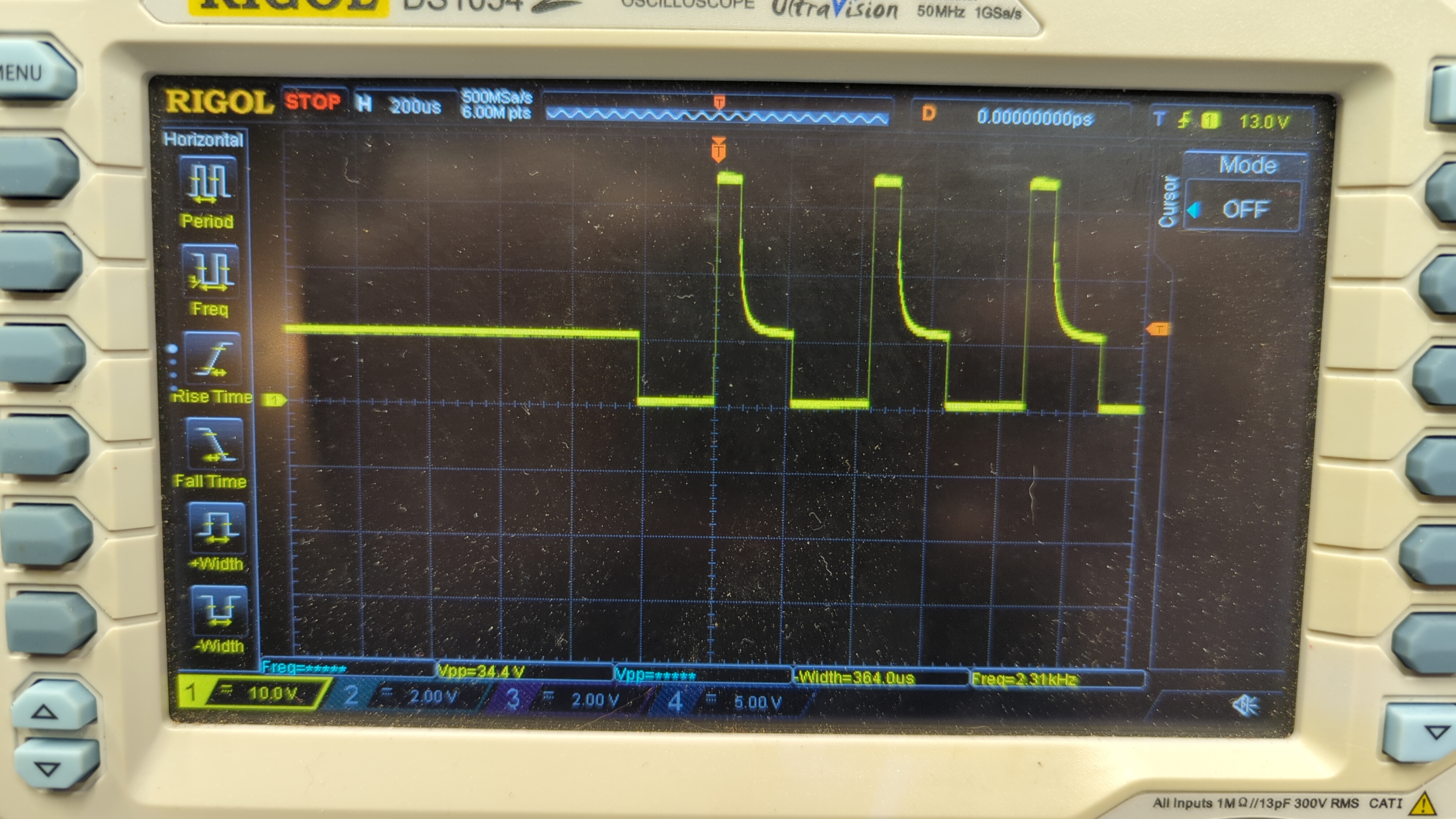
PWM is the solution to this problem. PWM only requires a digital signal, which is good for the microcontroller and good for the MOSFET. The catch is that both sides need to switch at the PWM frequency. I initially designed this frequency to be a comfortable 100 Hz or so, thinking that the solenoid body would absorb this low frequency. I was completely wrong about that, and my first attempts basically produced a loud buzzer that also happened to push piano keys. The best way to fix this is to push the frequency much higher, above the audible range for most humans (20 kHz)3. Having done that, I also realized that I’d need to include a flyback diode to avoid destroying the MOSFETs4.
That solves the interface problem, but we still don’t have enough pins to drive 88 keys on a typical MCU. Here I took some inspiration from Brandon’s design. He uses discrete shift register ICs in his system between the MCU and the MOSFETs. If I’m honest, I don’t fully understand their purpose5, but it gave me the idea to use ordinary parallel register ICs to buffer the MCU’s output. A sufficiently fast microcontroller can set the appropriate values for all the keys by iterating through each IC and setting the correct pin states at the proper times. This is the main principle of TDM. This also moves the burden of keeping 88 persistent output bits away from the microcontroller (where pins are relatively costly) to cheap register ICs.
To explain this more clearly, let’s examine the circuit in the diagram below, which focuses on a single key but is expandable to all 88.

I selected the Teensy 4.1 for its
speed, number of pins, and ability to act as a USB device, which will be
useful later in the project for receiving MIDI. (I also had one lying
around.) The IC in the middle is the 8-bit register (datasheet).
Whenever the register sees a rising edge on the CLK pin
(pin 11), it reads the binary values on each of the D pins
on the left (pins 2–9) and copies them to the Q pins on the
right (pins 12–19). In this circuit, the first data pin is connected to
digital pin 0 on the Teensy, and the clock pin is connected to digital
pin 13. When the Teensy wants to set the value of 1Q, it
first sets the value of 1D and then sends a pulse to the
CLK pin. The register then copies the value from
1D to 1Q.
The Teensy is a 3.3 V device, but the MOSFET I’m working with right
now works best with a higher gate voltage. In the future I might switch
to a different MOSFET without this property or just try 3.3 V directly
and see what happens. For now, I’ve included a BJT common-emitter amplifier
that uses the output of the Q pins on the register IC to
switch a 5 V signal from the Teensy. (The VIN pin is
nominally at 5 V when the Teensy is powered by USB.) Notably, this
inverts the signal, so I have to account for that in software.
This design is overkill for a single key, but my intention is to expand it to 88 keys. To do that, I’ll first have to connect the remaining 7 bits to some digital pins, and then I’ll add another 10 register ICs with the same connections. They’ll all share the same data pins, but each will have a separate clock pin. In total, only 19 pins are needed on the Teensy—eight for the data pins, which are shared among all registers, and 11 clock pins. The Teensy can set the data pins to any values, and the register ICs will ignore them until the Teensy sends a pulse on any of their clock pins. This allows the Teensy to reuse the data pins between all registers over time, dividing its attention among all the keys.
See the video at the top.
In the video, I’ve temporarily set up the solenoid to press a single key by clamping it to the piano. The driver circuit is on a breadboard, and I’ve set up the code on the Teensy to read the state of a push button and use that as input for the key. The code can currently handle 32 simultaneously pressed keys, although I haven’t tested this limit, so it may be more or fewer in reality. In this test, I set the velocity to 64 out of 127, and anecdotally the sound is in the moderate range. It’s probably possible to adjust the force profile across the velocity spectrum to give any desired behavior.
Here are the design parameters for the solenoid in the video, which is the best design I’ve come up with so far:
This design is too wide by about 2 mm, so I need to trim it slightly in a future iteration, but I don’t anticipate that being an issue. This will probably reduce the force somewhat, but I think that’s acceptable in exchange for being able to pack all the solenoids in a tidy row.
The solenoid rattles when it hits its top or bottom position. There are two likely causes. One is that the plunger sits on top of a plastic plunger extension, which the plunger pushes out the bottom to move the key. The plunger and its extension are not rigidly connected, and there isn’t any padding between them, so their small collisions make a clicking sound. Similarly, the bottom of the plunger extension is bare plastic, so it clicks slightly when it contacts the key surface. I think it will be easy enough to fix the second problem with some stick-on felt circles that are usually meant to prevent chair legs from scratching floors. I’m not sure yet what the best solution might be for the plunger/extension interface, but I’ll probably start with ordinary glue and see how that performs.
I printed the non-metallic parts in PLA with a 0.6 mm nozzle and 0.3 mm layer height. The most practical way to print these parts puts the layer lines perpendicular to the motion of the plunger, so I think it’s possible that the plunger could catch on the layer lines and get stuck. I’ve observed this on benchtop force tests but not on the actual piano. If it becomes an issue, I’ll probably have to switch to a different material. That would help with a related problem, which is that PLA begins to soften around 60 °C. It’s possible—even easy—to reach that temperature after a few minutes of continuous use, at which point the solenoid structure warps and makes it difficult for the plunger to move. I might explore using nylon tubing for the central cylinder section and printing the rest, or something like that.
Overall, I’m happy with this solenoid design, but I know it can be even better. I want to spend a bit more time optimizing it before I commit to building the full system. I’ll probably do a test with a single octave as a midpoint between a single key and the full keyboard. Also, in the next part of this project I’ll improve the driver code further and try to add support for USB MIDI so I can send music from my laptop.
Not to be confused with time cost, which is high for this or any of my projects. Of course, I have to do something with my spare time, and if it weren’t for these projects then I’d probably end up just playing even more Factorio than usual.↩︎
It later turned out that plenty of cheap solenoids with the right properties were available from Chinese suppliers. I definitely could have saved some time by purchasing them, but I wouldn’t be as good as solenoid design as I am now.↩︎
This required some interesting code optimizations that I’m pretty proud of. I’ll discuss them further in a future post on this project, once the code is more mature. Also, if you’re thinking that it would be easier to reduce the PWM frequency instead, I had the same idea, but I just ended up shaking the test stand off my bench at 16 Hz.↩︎
Notably, while adding the flyback diode did help a lot, I noticed that there were still some high-frequency oscillations when switching off the solenoids. It seems that the diodes I selected—or more probably all diodes—have some small internal capacitance. Since this small capacitance is in parallel with the solenoid’s inductance, the flyback energy oscillates between them in a typical tank circuit. The oscillations die away quickly, but they still exceed the breakdown voltage of my current MOSFETs about 2% of the time, so I’ll probably address that by simply choosing a different MOSFET with a higher breakdown voltage.↩︎
My guess is that the shift registers in Brandon’s design do the same kind of thing that the parallel registers do in my design (that is, TDM), just in a different way.↩︎