
2023-12-25
TL;DR: I added a pen plotter attachment to my 3D printer and used it to draw custom Christmas cards. I also laser cut some envelope templates out of red and green paper.
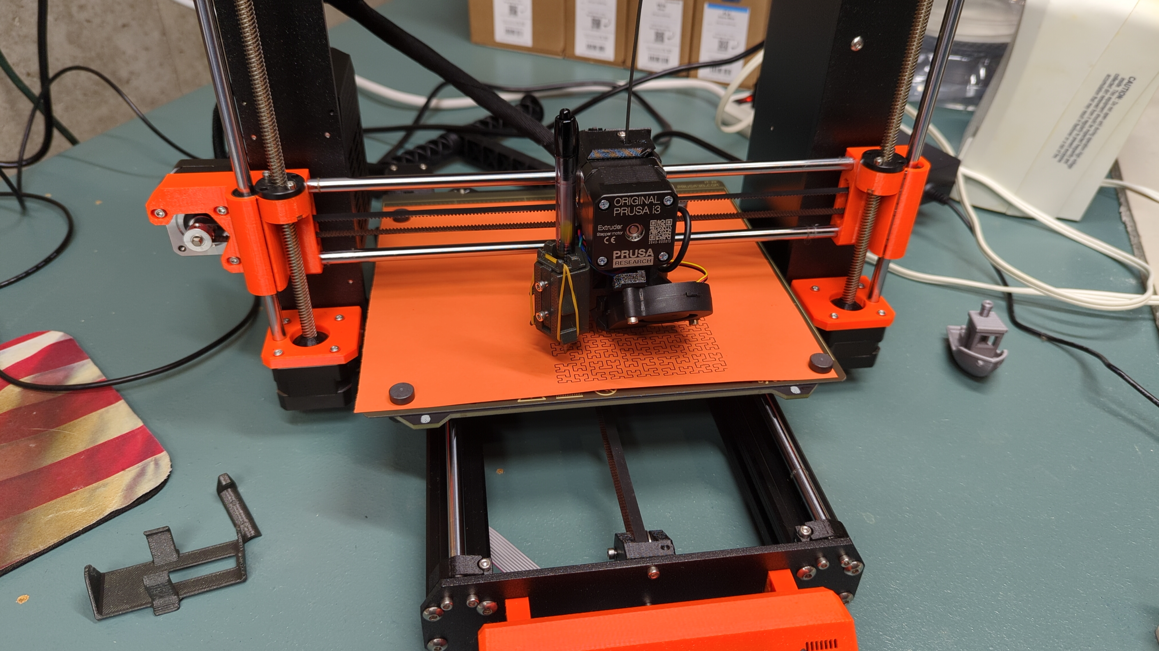
I started this project by accident. I was tired of printing Gridfinity bins for the lab, so I took a break from that and decided to try something fun. I already knew that a pen plotter is a machine that moves a pen over a surface and can lift it as needed to create a drawing. It occurred to me that my 3D printer already had nearly all of those capabilities, except it couldn’t hold a pen. Since my printer model is popular, I supposed that someone must have thought of this before and put a design online. I was correct, so I downloaded the design that I found and printed it up.
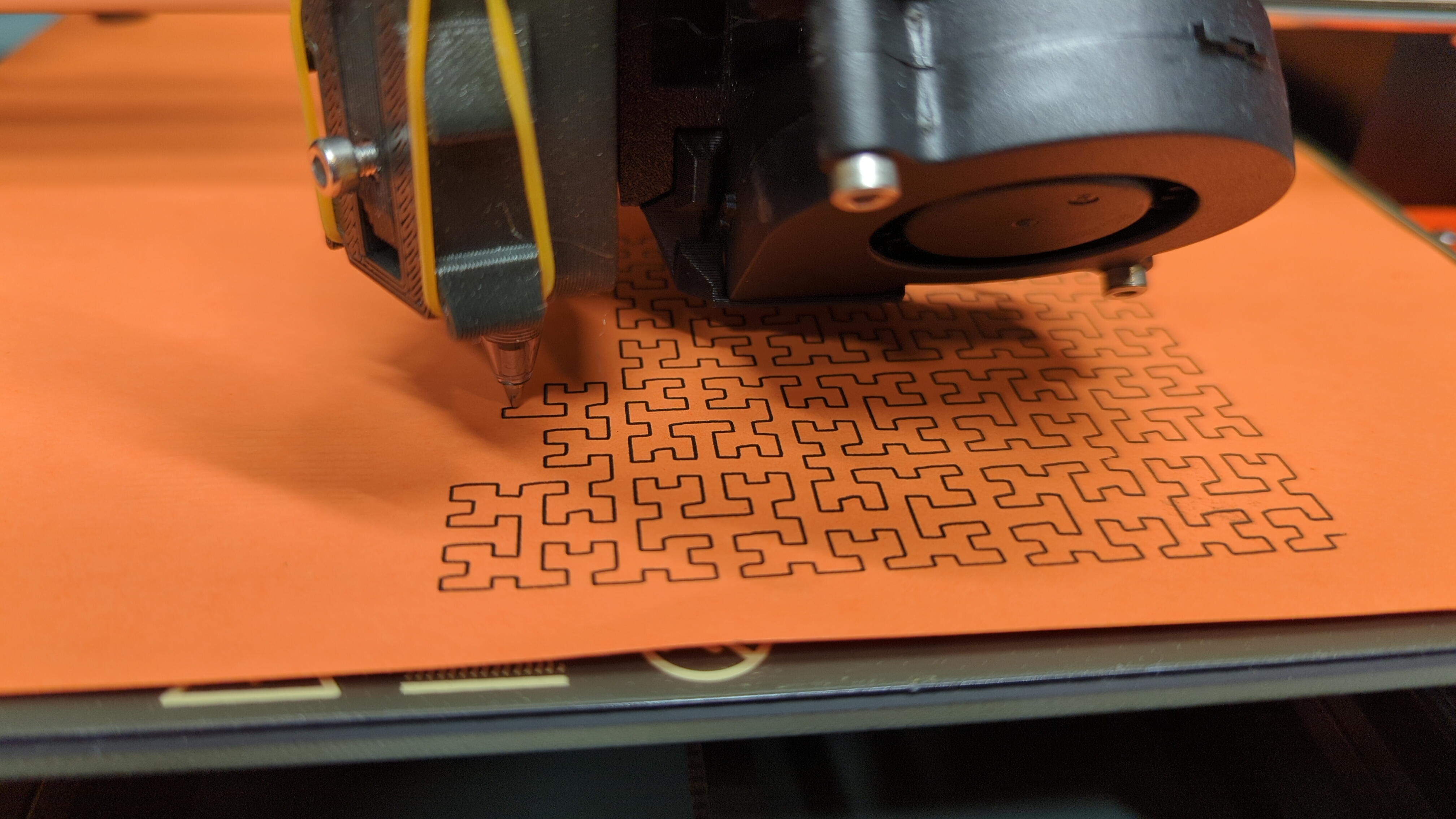
The plotter attachment’s design is clever. It uses the existing screws that hold the extruder fan on to hold itself on as well. The pen is inserted in a separate part that has two set screws for keeping the pen in place. The pen and pen holder are inserted together into the main housing, and the pen holder is free to move in the vertical direction. The design calls for a rubber band to be looped over the top of the assembly and wrapped around hooks on either side. The rubber band keeps the pen holder firmly against the main part, but it also allows for some vertical motion when the pen contacts the surface. This gives the design some tolerance to imprecise vertical positioning and helps to prevent damage to the pen or the machine.
Installation was easy. The plotter model came with some test Gcode,
but it was up to me to supply the Gcode for designs I actually cared
about. For this, I used a lovely tool called svg2gcode
that does exactly what you’d expect.
I found during some tests that thin paper (i.e., ordinary printer
paper) likes to curl when the pen has been working on it for a while. I
tried using magnets to secure the paper at first, but small binder clips
seemed to work better. The thicker paper that I used later in this
project didn’t have this problem. svg2gcode allows the user
to submit custom “tool up” and “tool down” sequences, which I copied
from the example files that came with the plotter mod and further
modified to suit my needs. I found 6 mm and 3 or 3.5 mm for the up and
down positions to be just fine, depending on the paper thickness.
It’s somewhat difficult for me to guess exactly where a drawing will end up on the bed. The pen is offset from the extruder, so all coordinates are translated in the horizontal plane. For the most part I would make educated guesses, measure a bit, and then hope for the best.
To enhance the design, I thought it would be fun to create my own envelopes, rather than buying some generic ones. I decided to laser cut the envelopes in two parts, one in red and one in green. I call this a “grabber and flapper” design because one piece folds over the other along three edges and “grabs” the other one. The flapper is the part that folds down over the top edge. I used glue to secure the two pieces together. The finished envelope can hold a sheet of A6 paper.

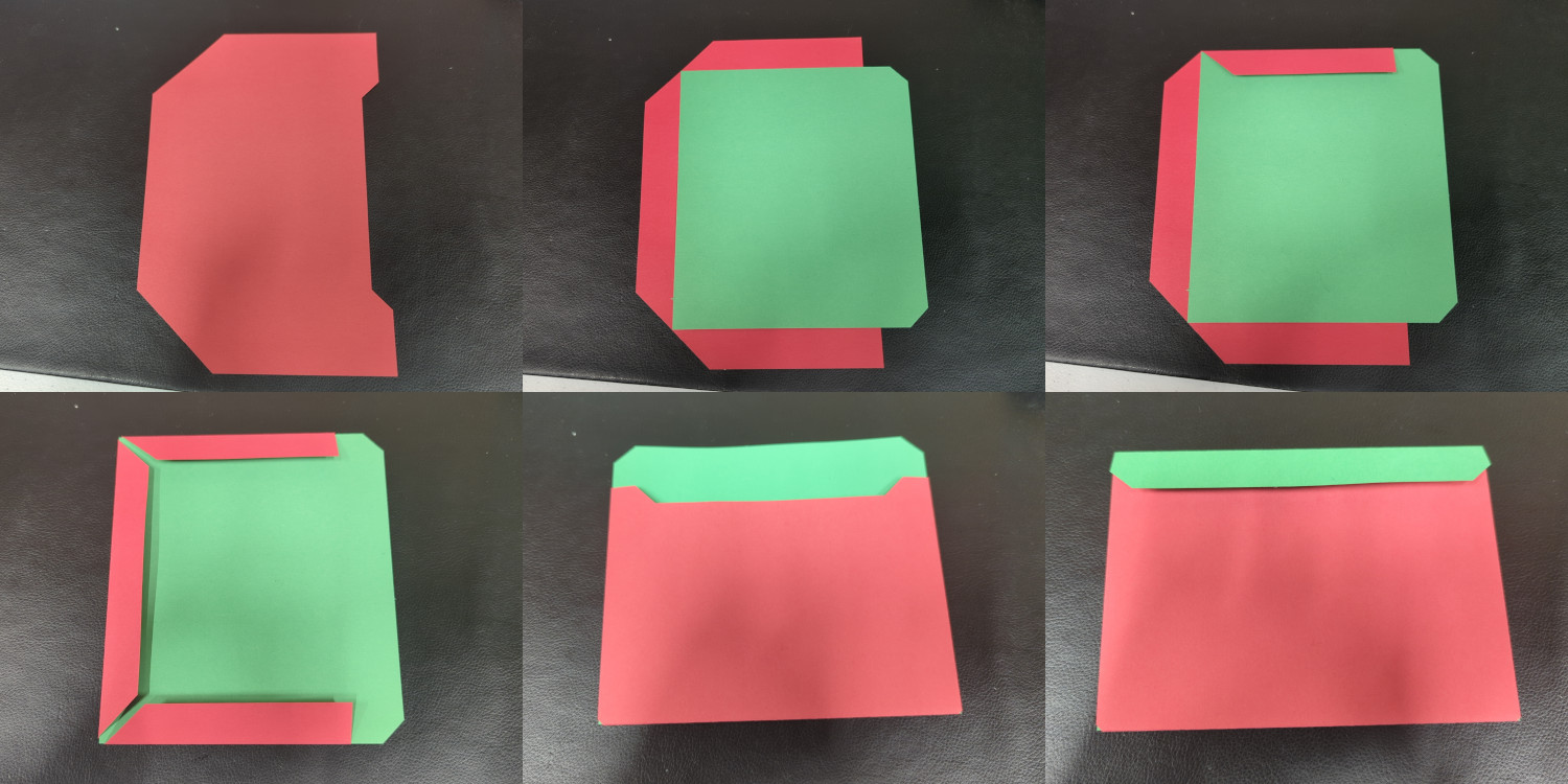
I like this design because it’s easy to assemble. Also, it’s possible to cut two flappers or two grabbers out of one US letter sheet of paper, which minimizes waste. I don’t care for how the grabber’s “arms” look on the back of the envelope, but I couldn’t think of an acceptable way to avoid that problem. A consequence of this design is that the front of the envelope (that is, the side where the address and stamp go) is the side with the flap, which is typically the back of an ordinary envelope. I like the way this arrangement looks in this case.
Having done all of the prep work above, making the cards themselves
wasn’t a big challenge. I selected a line drawing by Leiah M Jansen
that reminded me of a snowflake and paired it with some appropriate
greetings and well wishes for each recipient. I used Inkscape’s
centerline autotrace feature to convert the raster line drawing into
paths. After converting the text to a collection of paths as well, I set
the stroke width for all paths to 0.5 mm, which seemed to be the
approximate width of the Pilot G2 07 I was using with the plotter1. Since svg2gcode doesn’t support
filled paths yet, I chose a font size that would result in the outer
stroke getting “close enough” to a filled shape in most cases.
I also decided to laser cut the cards out of their larger sheets rather than cutting them by hand. To make this work, I had to align the sheets under the laser with good precision (~1 mm ideally). I solved this by adding two fiducial markers to my SVG design outside the final printing area and using their known positions to align the laser. The procedure I used was to align the first marker, move the laser to where it thought second marker should be, and then lightly poke the first marker with a metal tool so the sheet would pivot around it. I could then align the second marker, and then I was good to cut. The laser cutting did leave some soot on the edges of the thick cardstock, so I wiped them down before putting them in the envelopes.
All I had to do then was address the envelopes, add the cards, seal the envelopes with some glue, put on some stamps, and drop them in a mailbox.
I took a brief diversion during this project to explore the possibility of converting raster images into a suitable representation for plotting. This isn’t trivial for a few reasons:
These limitations force any solution to essentially become a lossy compressor of the input. When a human artist sketches a subject, they are doing exactly that. The medium can’t support a naive translation of the input, so the artist has to use their skill to select what parts of the scene will stay and discard the rest. Somehow the artist has an approximation of the target function (i.e., human visual perception) embedded in their brains and can use it to iterate towards an acceptable solution. An optimal solution to this problem must do the same thing.
Of course, that’s a lot to ask for in a week of messing around. I
suspect a modern AI system somewhere can already do this, or could be
made to do it easily3. For now, I’ve combined some other
approaches that I’ve seen online and built a cute little program called
scribbler that does the conversion.
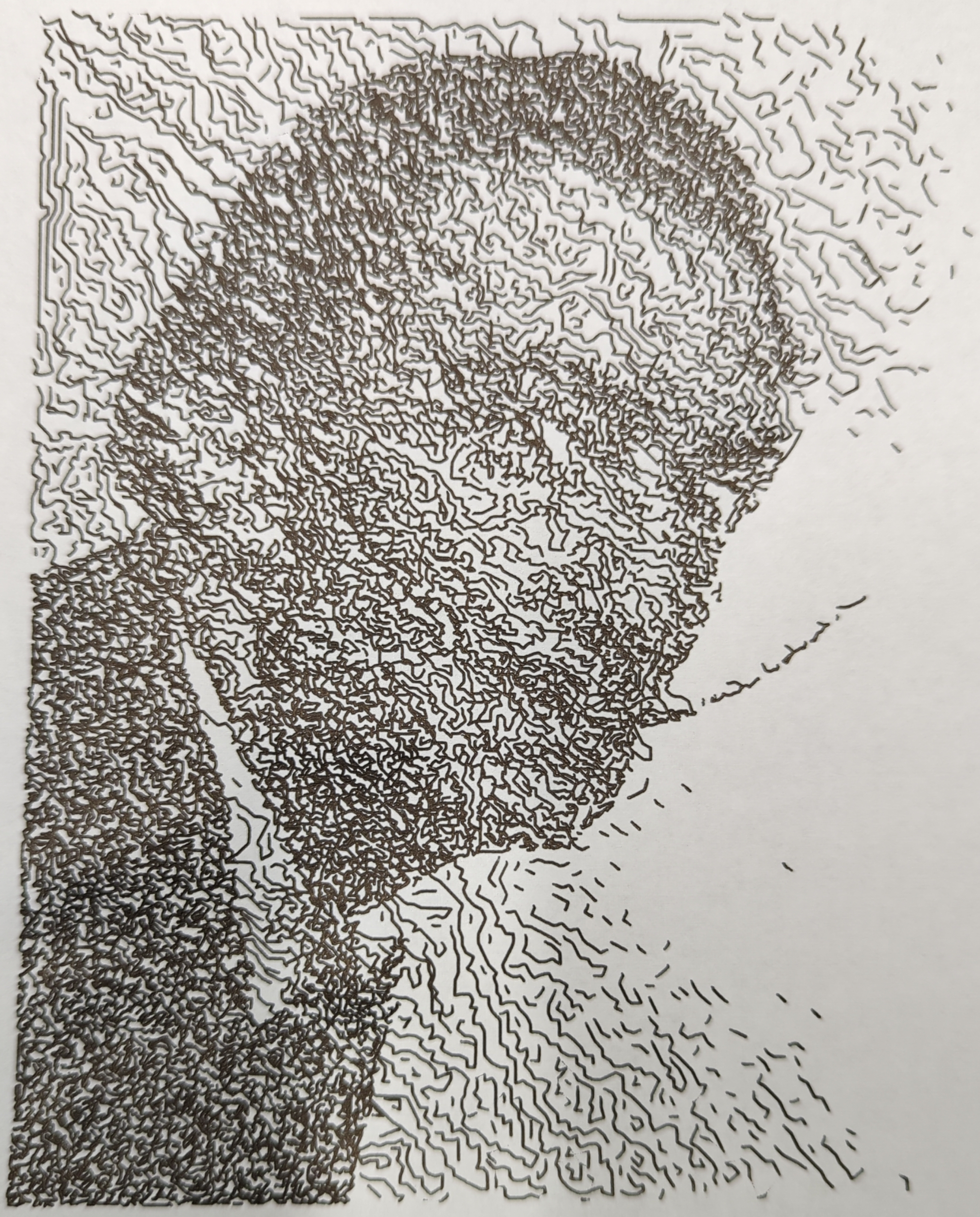
To start, I first scale the input down to the desired size, accounting for the width of the pen. For example, if I want the image to be 200 mm tall, and the pen makes a line that’s 0.5 mm wide, then the scaled height of the input should be 400 px. After scaling, I apply binary dithering. This converts the input into an arrangement of white and black pixels. Finally, I choose a random black pixel and run a depth-first search over the pixel’s black neighbors. This links the black pixels into a collection of segments that I can then convert to SVG paths for plotting. This results in an image like the one above.
“Good from far, but far from good.”
I think/assume that the “07” means that the line width is nominally 0.7 mm wide, but I ran some experiments with my particular setup and found that it’s more like 0.5 mm.↩︎
That is, the pen can only produce binary output with this system. Human artists and more sophisticated machines can certainly achieve some gradient between zero and maximum ink.↩︎
There are also other non-AI systems that will approximate an input using e.g. circles of varying radius and spacing.↩︎