2023-02-14
Last year, I planted some beans, potatoes, and tomatoes in our garden. I made an uninspired attempt at a low fence, but this didn’t stop local wildlife from munching on the bean plants and ruining my crop.1 I vowed to build a vegetable fortress in the following year. Well, here we are. I can’t build the fence right now, but I sure can design it and be ready to go when the ground thaws.
I didn’t think it would be that hard. Fencing seemed trivial—just put
down a few posts, stretch some chicken wire between them, and you’re
done. Guess what: it is not trivial, at least if you
try to do it well. Of course, I probably could have cut a few corners in
the design and figured things out on the fly, but that’s not how I like
to operate. Why make frustrating and potentially expensive mistakes
later when I can overthink thoroughly plan now? I
don’t imagine that I’ll avoid all frustration later through
planning—there will definitely be unexpected problems—but I’m not so
good at thinking on my feet, so I’d like to use that limited resource
where it’s absolutely needed. Plus, during all this planning and
thinking I learned some new skills in FreeCAD and gathered a good deal
of new knowledge about basic construction.
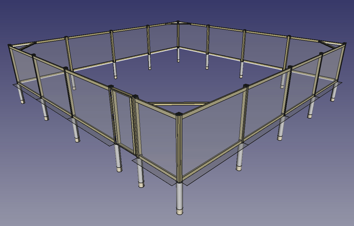
Posts are critical for good fencing. If your posts sag or don’t line up, then your fence will look bad or even collapse. The first step is to use stakes and some string to lay out the fence on the ground and get everything lined up. Then it’s a good idea to mark out the locations of all the posts. My garden fence will be a 32’ square, and the posts will each be 8’ apart. Add one more post for the gate to swing on, and that’s 17 posts. The recommended way to mark the post holes seems to be with spray paint, although I’m a little skeptical about the precision and necessity of the paint when additional stakes or even small “starter holes” might be better.
Some amount of the post should be buried in the ground so it doesn’t fall over, and the rule of thumb seems to be that about a third of the post’s total length should be below ground level. I intend to use 8’ posts, so 2’ 6” will be buried, leaving 5’ 6” of apparent post height. I’ll also secure the posts in the ground with concrete. I’ve gotten some conflicting data on how much concrete is necessary. Some sources on the Web seem to claim that the diameter of the concrete cylinder surrounding the post should be three times the width of the post itself. For a 4”×4” post2 that means the concrete diameter should be around 10”. This turns out to be a lot of concrete. By my math, I’d need about 45 80-lb bags of concrete mix, or almost two tons of concrete. That seems like way too much for a little garden fence.
My grandfather—who seems to have built at least one of everything in his life—told me that a 6” or 8” concrete diameter would be quite enough. That was a relief, since a 6” diameter would only require about 11 bags of 80 lb each. I suppose there’s a chance that the Web is correct and I actually need lots of concrete, but I’m willing to take the risk.
Actually digging the post holes is another challenge. I need to go 3’ down3 17 times without taking too much time or effort. The tool for this job is an auger, which is a sort of screw that burrows into the ground and brings the displaced dirt to the surface. Plug-in electric varieties with 6” bits may be had for $200. I considered renting one, but the closest place I could find was about an hour away and still wanted $100 for one day. Might as well buy it.
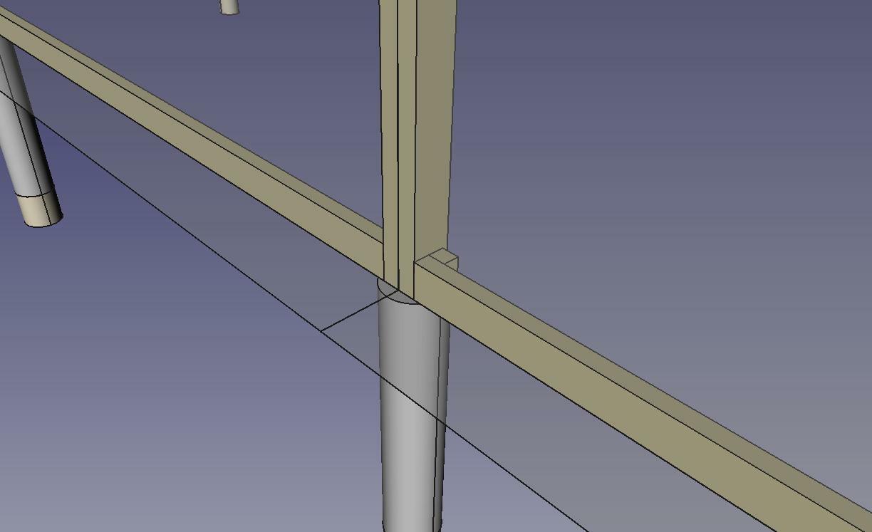
The concrete should be mixed with water in a wheelbarrow or similar. After adding gravel to the bottom of each hole, I’ll stand each post roughly level and centered and attach some temporary bracing made from scrap wood. Then I’ll pour the concrete in, level the post, and get the braces set so the concrete can cure over a few days. The concrete should also be formed into a slight hill away from the post so rain will run away from the wood. It’s not clear to me yet how I’ll make sure that all the posts are as close to the right distance apart as possible, but I guess I’ll work that out with my grandfather’s help.
After the posts are set, I’ll add some caulk to the seam between the concrete and the post. Supposedly the natural growing and shrinking of the wood over the seasons will cause a gap to appear where water can get in and accelerate the wood’s decay, so sealing it up helps to prevent that.
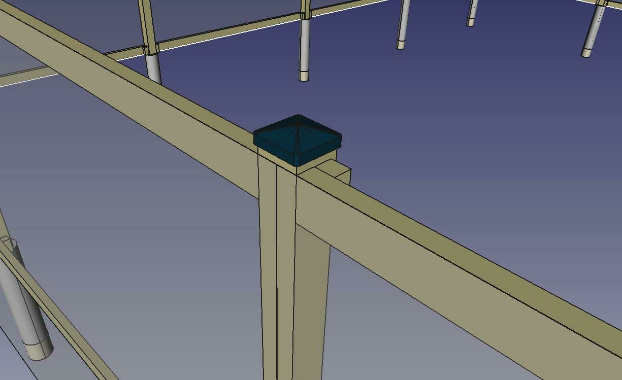
Finally, I’ll add some metal post caps to the tops of the posts to protect the upper faces from rain. After that, it’s on to adding rails, chicken wire, and the gate.
Ordinary lumber will rot quickly if left outside or buried in the ground. For this reason, exterior woodworking projects depend on chemical preservation techniques that protect the wood from moisture, insects, and fungi. The wood I intend to use is treated for ground contact, which means it’s safe to bury and fully expose to the elements. The chemical treatment involves dissolving small copper particles (less than 1 µm) in water and injecting the solution into the wood. It’s not clear to me exactly what “injecting” means here—some sources I’ve read aren’t specific—but I have to imagine it just means soaking the wood in the solution, perhaps under pressure or heat to accelerate the process. Copper treatments are considered safer than previous methods, which often used arsenic.
Chicken wire4 is an inexpensive barrier that provides reasonable protection against mostly-unmotivated varmints. It’s nothing more than galvanized steel wire arranged into a sort of loose fabric with holes around an inch across. A common design pattern—and one which I intend to use—is to attach the chicken wire all the way around the outer edges of the fence posts and rails. I’ll use staples ejected from a pneumatic staple gun. The chicken wire I intend to buy comes in a 6’×150’ roll, which is more than enough to go around the whole fence. That height dimension leaves me with an extra 6” to play with, so I think I’ll bend it outward along the ground like a skirt to prevent critters from digging under the bottom rail.
This part of this project turned out to be a good use case for a spreadsheet. My goal was to determine the overall price of materials given some assumptions about the design, and I achieved that without too much effort. The most difficult part was thinking through the design and what materials would be required, which I took to be a good sign. I could tell that this was an effective approach to documenting this part of the design process. I linked to the Home Depot product listing for each item, and then I computed the amount of each item that I’d need, plus a waste factor of 15%. When the time comes to make the order, all I’ll need to do is go down the list.
I also took some time to think about how much labor will be required in order to actually do the construction. I like to use the following technique when estimating durations for future tasks:
This helped me to figure out how much effort I should expect to apply to this project. It also forced me to think about the physical steps I’ll need to take to get the materials where they need to be and arrange them into a fence shape.
CAD is a high-variance activity for me. Sometimes I feel intense frustration at the software and everyone who ever thought it was a good idea, and other times I feel like a God of Matter.
I used this project as a motivator for learning assemblies in FreeCAD. Assemblies are an abstraction that allow the designer to compose multiple part models into a larger arrangement. In software-speak, this helps to separate the concerns of different parts of the system and defines the interactions between those parts with clean interfaces. I used the Assembly4 addon to provide this set of features, and overall I found it relatively easy to get started making stuff.
The core feature of Assembly4 is the Local Coordinate System (LCS). Every assembly has at least one LCS, and assemblies interact by linking to each other by their LCSes. For example, a designer might specify that the LCSes for the center of a screw and the center of a hole should be locked together in space. The screw and the hole are in different part models, but the designer can link them together in the same assembly and compose them without the individual parts needing to know or care. Perhaps the best part is that any changes to the underlying part models in their respective files will show up in the larger assembly. What you end up with is more or less a tree where the top-level assembly is at the root and all the parts and subassemblies form the branches and leaves. Every edge in the tree is a link between the LCSes of two models. LCSes may also have some fixed translation and rotation between them.
I felt some frustration with Assembly4 at times, but I’m pretty sure the root cause was my own lack of skill. As the project progressed, I could already recognize some of my earlier mistakes. I’d say my biggest mistake was not thinking hard enough about the LCSes before I started modelling. Like structuring a large program, it seems like it’s important to define the LCS interfaces first before getting too far into the project. To be fair, the Assembly4 docs do explain this pretty clearly with the concept of a “master sketch”. I’m excited to apply this new knowledge in future projects.
I have one problem with Assembly4. In my mental model of FreeCAD, parts are like functions that have local scope and produce some model as output. The model has LCSes and may be integrated into a larger system. These “functions” can even have local variables, which Assembly4 supports readily. I think something is missing, though. It would be nice if there were a way to pass arguments into these “functions” and get different output. For example, I would have liked to be able to pass a length parameter to the fence panel model that I built. The fence panel would use that input to change its resulting length, and I could reuse the same model in multiple places. It seems like this kind of thing might not be possible in Assembly4 at the moment, although I’m not certain because I don’t know how to search for it. If I could somehow get this sort of feature working, then I would consider Assembly4 to be complete and wonderful.
While designing the fence in FreeCAD, I was able to show my grandfather the design through a screen share. I asked him for advice and his opinions on certain design decisions, and he helped me to make serious improvements to the stability and constructability of the design overall. This was a special experience for me because I’ve always looked up to my grandfather’s mechanical ability, and now he and I have gone through a “design review” on something I’m going to build. I hope to remember this for a long time.
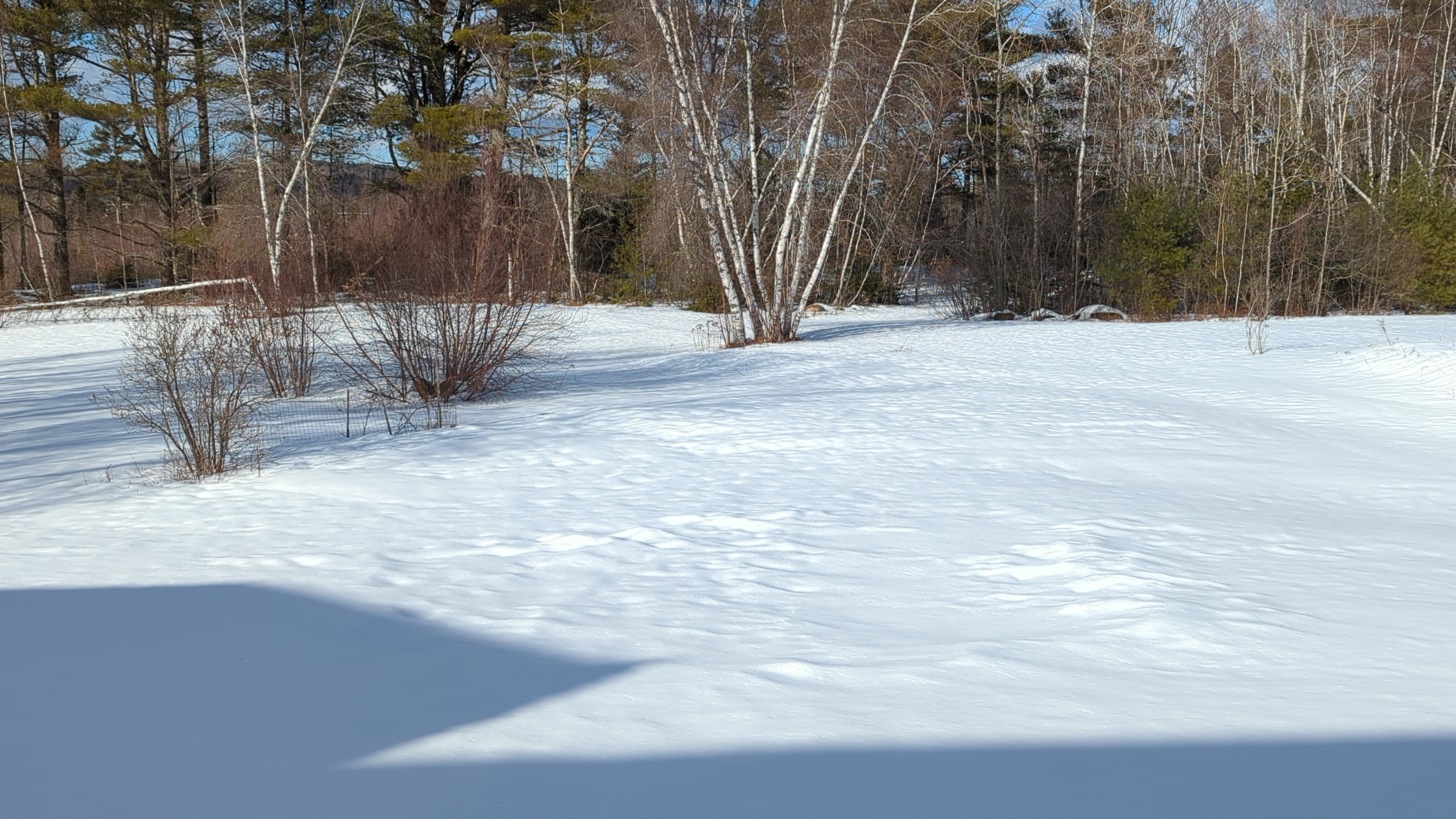
There isn’t much more I can do except wait for the weather to change so I can begin construction. My plan is to make one big order at Home Depot, borrow my grandfather’s truck, and bring everything home in one trip. I expect that to take most of a day, and I expect actual construction to take two or three weekends, depending on my energy and skill. The earliest I expect to be able to start is in late March, but sometime in April is probably more realistic.
In particular, a neighbor’s goats have a habit of getting loose, and they seem to remember the path to our garden quite well.↩︎
Which is actually 3½”×3½” because dimensional lumber is a bit weird.↩︎
2’ 6” for the post, plus another 6” for a gravel layer, which somehow helps with the concrete’s stability and has been recommended to me in several places.↩︎
Or “poultry netting”, as a few upscale product listings have called it.↩︎
Multiply (1) and (2) together, and then take the square root.↩︎