2022-11-22
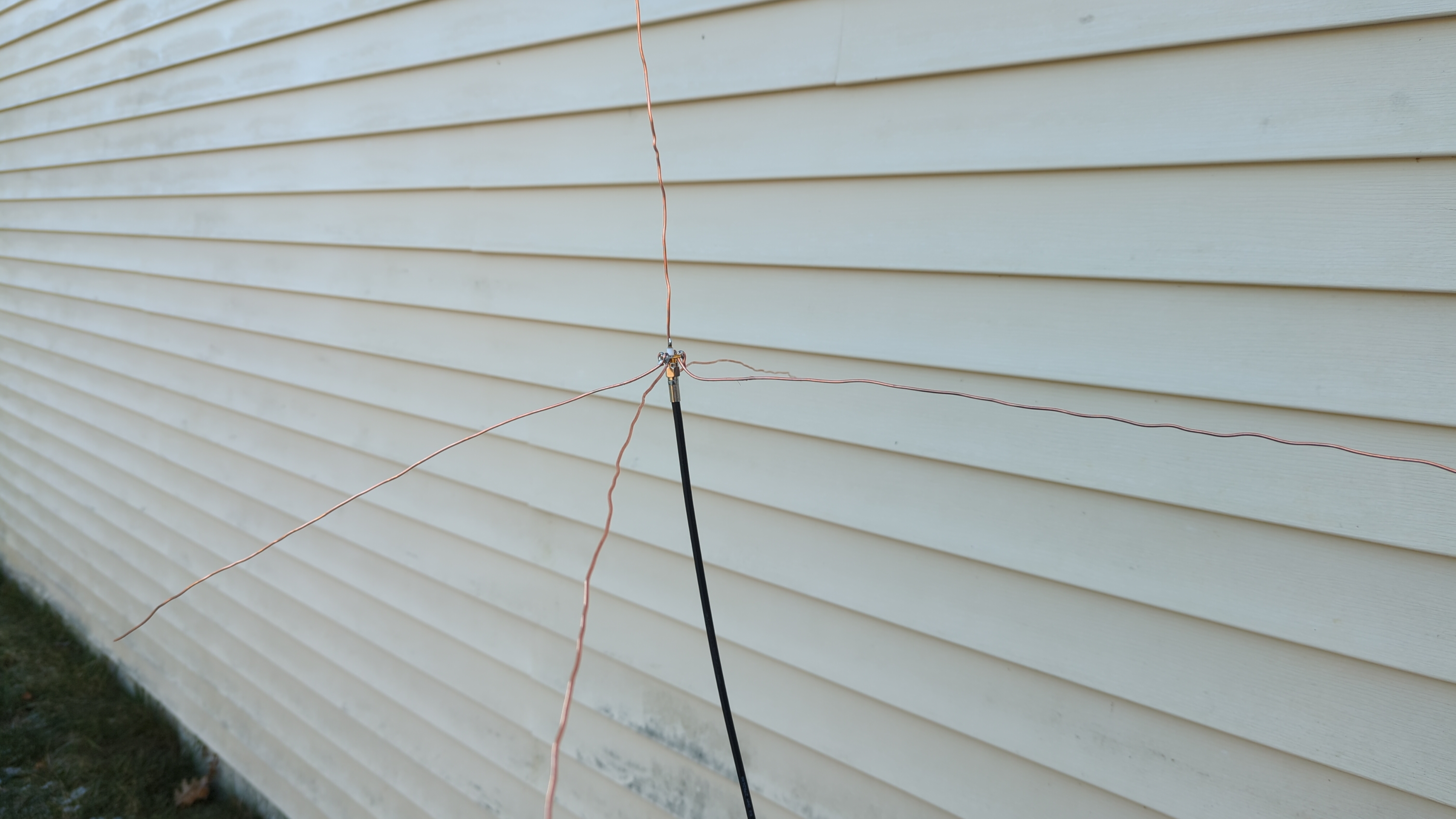
The antenna works. 🎉 Here it is:
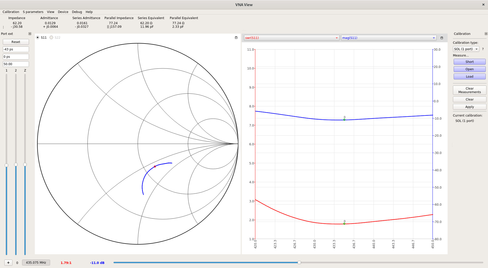
I bought a nanoVNA in order to measure my antenna’s performance in the frequency range I care about. The nanoVNA optionally connects to a typical computer over USB and sends data to a viewer application. Here’s the nanoVNA output for the antenna over the two-meter band (144–148 MHz):
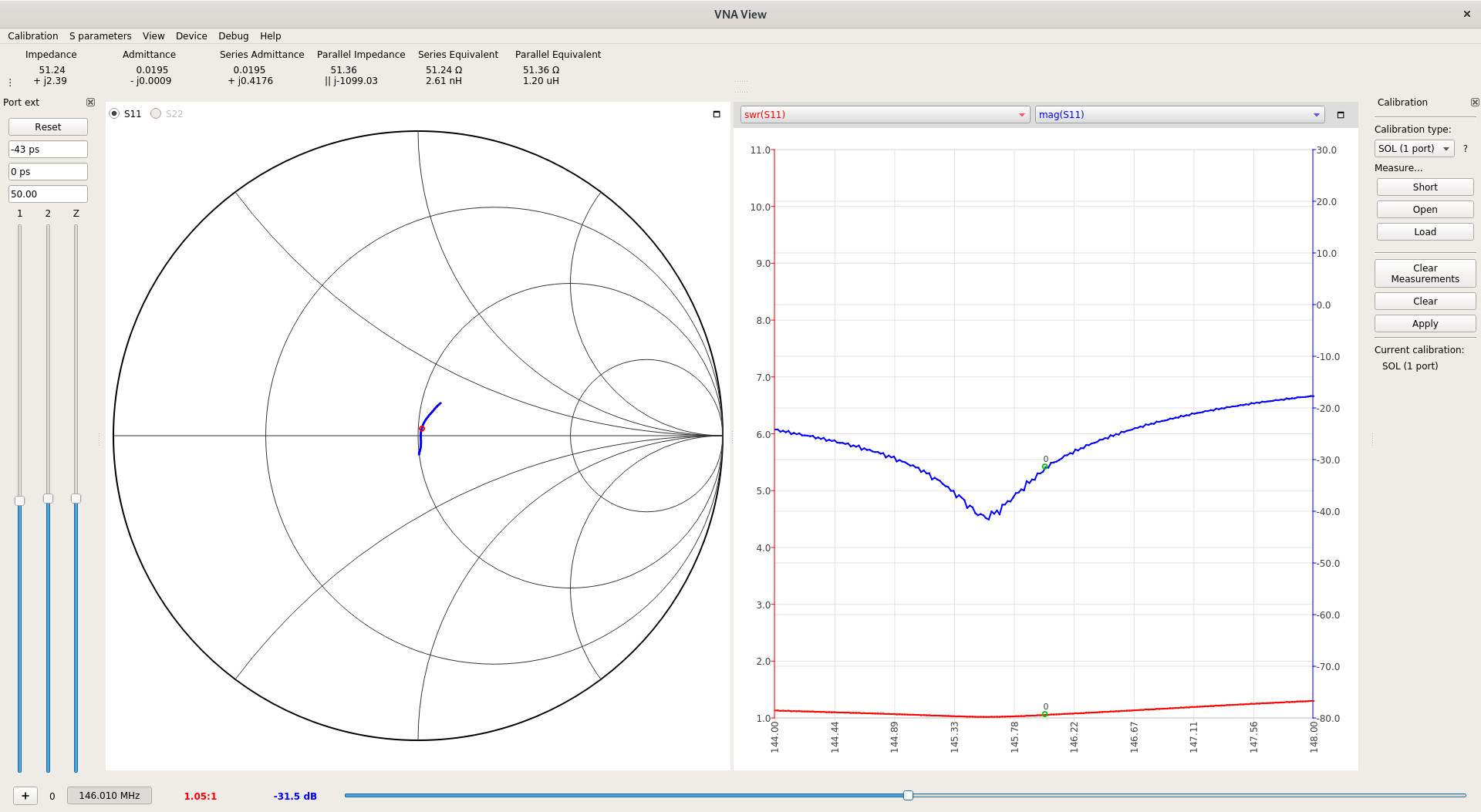
Reading these charts is easier than it might seem. On the left is a Smith chart, which shows how an antenna (or any device under test) responds to signals with known frequencies. The nanoVNA sends the known signals—usually by sweeping over the frequency range—and records the equivalent impedance that it measures. Recalling that impedance is a complex value, the Smith chart represents all values from an open circuit to a short circuit by mapping a portion of the complex plane onto a circle. Resistance runs from zero on the far left to infinity on the far right, and the top and bottom halves correspond to net inductance and capacitance, respectively.
Our goal is to match the impedances between the radio/cable system and the antenna. A good match means that most of the power from the radio makes it into the antenna and into the air to be received by someone else. A bad match means that some of the power is reflected back into the radio, which heats up the radio and does nothing useful. A perfect match would show up as a dot in the center of the circle, which by convention indicates 50 Ω with no net reactance.
In this case, the antenna is close to a perfect match over the entire two-meter band. The blue curve on the Smith chart shows the equivalent circuit that the nanoVNA measures at the calibration plane, which I set to be the antenna connector. It’s not practical to get a perfect match over a range of frequencies because most real systems have some variation in their frequency responses, but as long as the bulk of the curve is close to a perfect match, the antenna is quite useful. In the middle of the band (146 MHz), the nanoVNA measures the antenna at about 51 Ω with very little net reactance, which is more than close enough for me.
The match is confirmed by the plot on the right. The standing wave ratio (SWR) is shown in red. This value shows the same thing as the Smith chart (i.e., how close the match is), except that it doesn’t say anything about how to improve the device under test. An SWR of 1 is a perfect match, and the antenna shows an SWR below about 1.3 throughout the whole band, which is quite good. The amount of power reflected by the antenna is shown in blue in decibels (dB). A lower value here is also good. We’re below -20 dB throughout most of the band, which means that less than 1% of the input power is reflecting back.
Compare these results with the same measurements for my old rubber duck antenna that came with the radio:
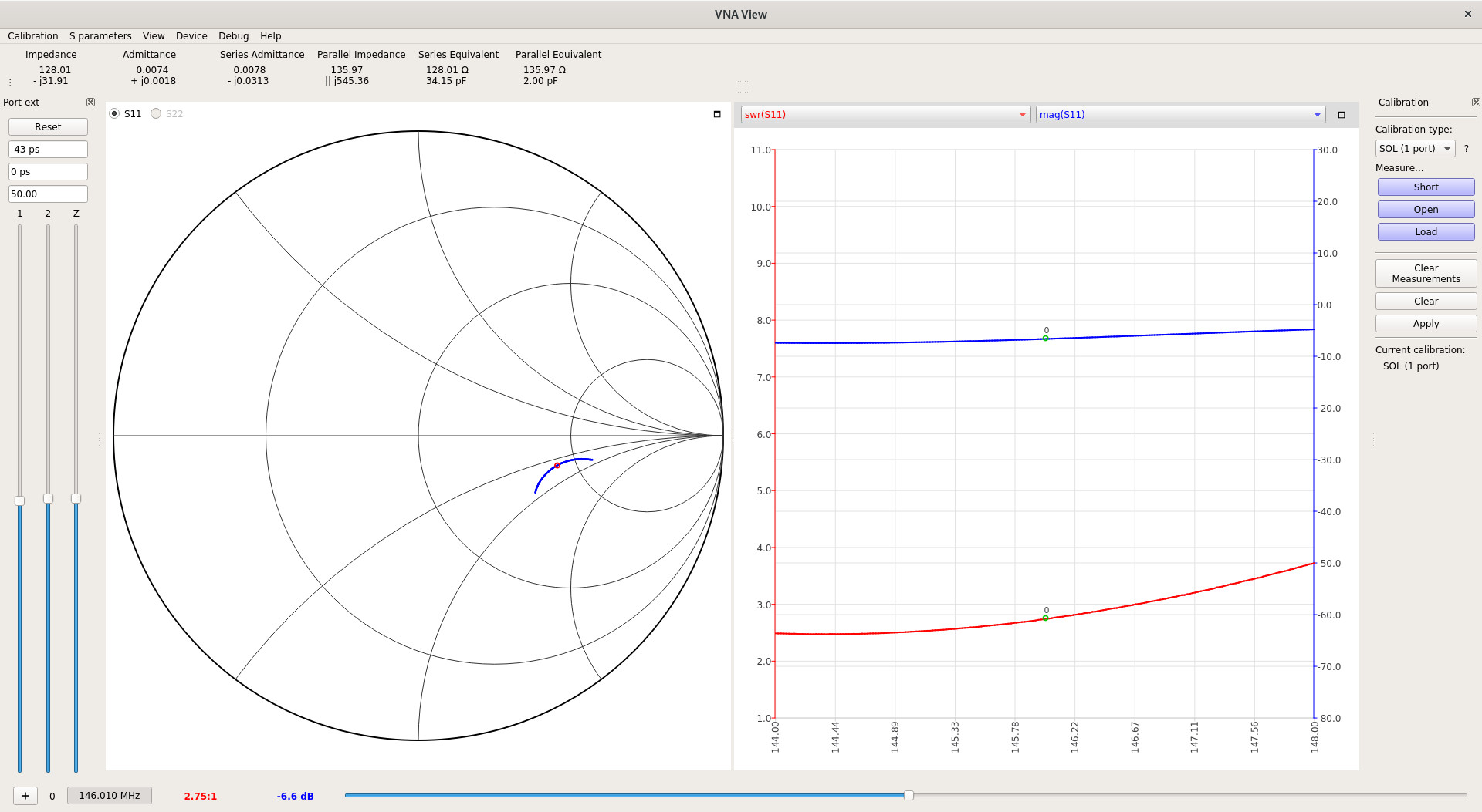
The Smith chart shows that the antenna has some net capacitance and too much resistance on two meters1. This results in an SWR of around 3 for most of the band, with around 20% of the input power being reflected. That explains why I’ve noticed my radio heating up after transmitting with the old antenna for a while. That doesn’t seem to happen with the new antenna.
Just for fun, I also measured the frequency response of the old antenna over the 70 cm band, since it’s sold as a dual-band antenna. It does perform slightly better, which I guess must be because it’s physically short and somewhat closer to the wavelengths in play around 430 MHz.
I made a contact with another ham in my area with this antenna. As a practical test, I gave him a before-and-after comparison between my old rubber duck antenna and the new ground plane. He told me that the signal from the ground plane was much clearer. I also noticed that my radio wasn’t heating up at all during transmission, which makes sense because a well-tuned antenna doesn’t reflect much power.
Later, I made a contact on a different repeater that’s about twice as far away (~20 miles). I also played with the Automatic Packet Reporting System, which is a short data message protocol meant for local reports of useful information, such as weather and vehicle locations. APRS stations store and forward packets for other stations to hear. Typically, operators connect the audio input and output of a computer with proper software to their radios, treating the radio kind of like a dial-up modem. (This is a common architecture for other digital modes.) In my case, I don’t have the proper connector between my radio and my laptop, so I improvised with a cheap microphone:
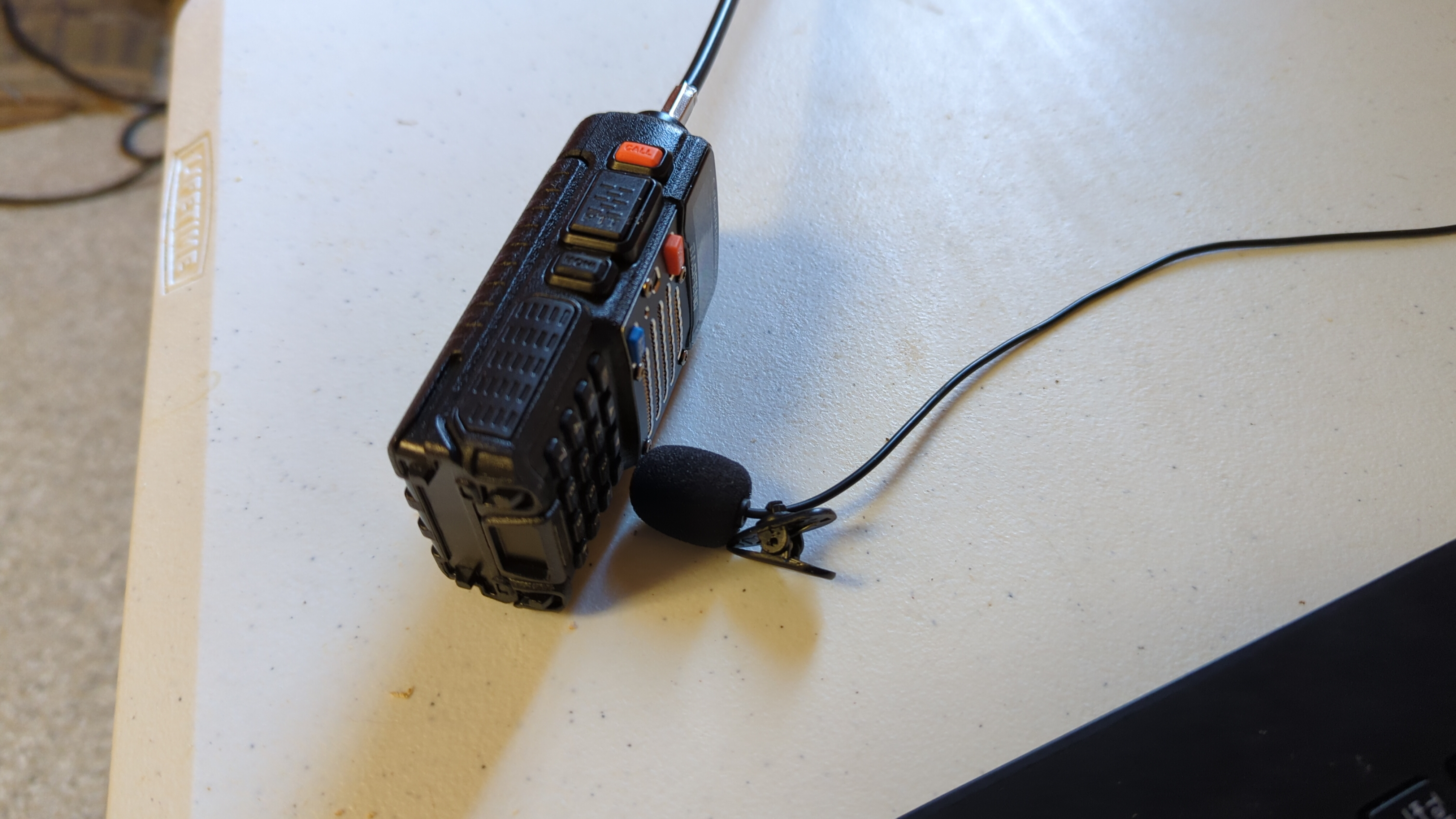
This actually works somewhat well, and I can decode a decent number of the messages that come through. Maybe someday I’ll get the right connector, which would also allow me to reasonably transmit. I didn’t try that here because I suspected it would fail, and sending bad transmissions isn’t good for anyone.
As a part of this project, I learned how to attach connectors to coaxial cable. It seems like there are actually a few ways to do this, but I chose crimped connectors, which have little metal cylinders called ferrules that you squeeze onto the connector and cable with a special tool. The friction of the squeezed metal keeps the connector in place. This wasn’t too hard, but I mention it because it was kind of hard to find information about how to do it on the Web. There are so many connector and cable standards that I couldn’t find an example of what I was trying to do, and I wasn’t certain what ideas were relevant to my case.
I used RG-58 cable and standard SMA connectors. The process I followed was to strip the ends down to the conductor and then just the jacket a bit further up. It’s important to remember to slide the ferrule and heat-shrink tubing on no later than this point. Then I soldered the pin or jack onto the conductor, spread the shielding, and applied the connector. I crimped the ferrule, and then I was done.
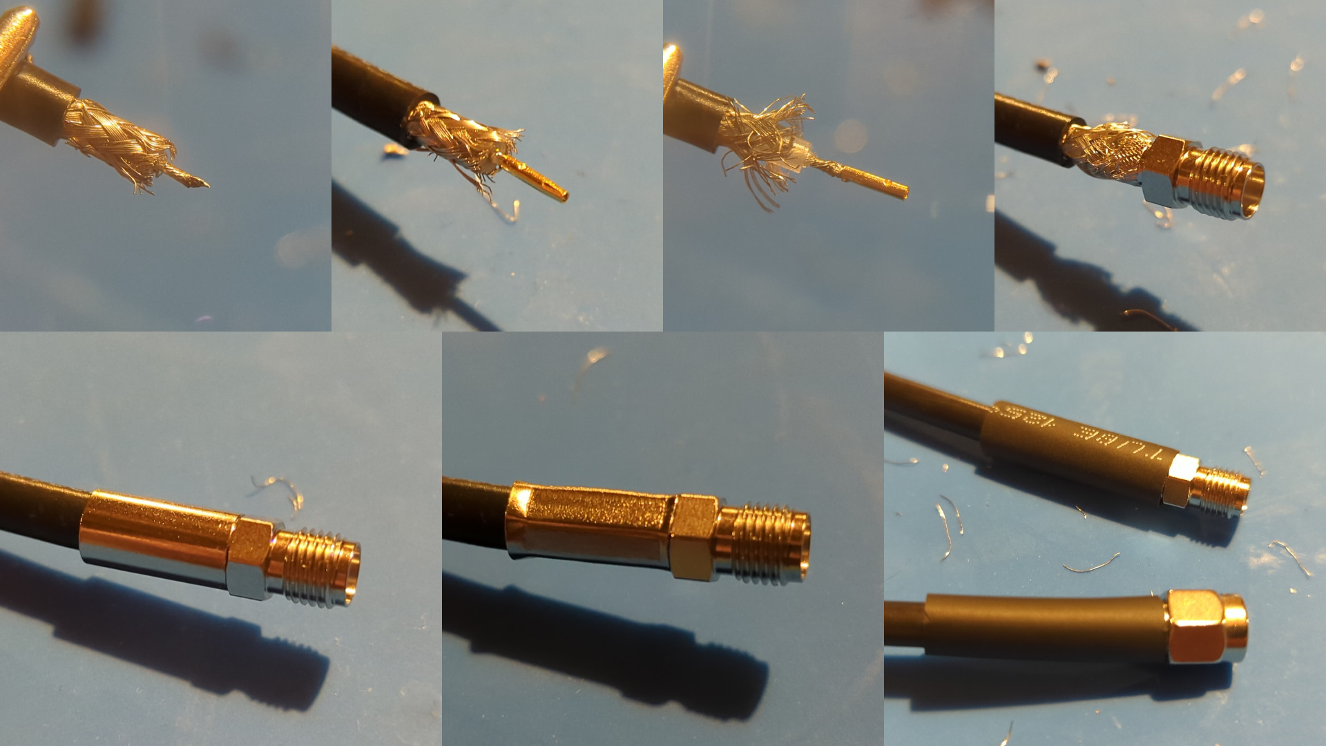
Soldering the pins took a little practice, and I did fail once or twice, but after that things went pretty smoothly.
The antenna didn’t start out with a good impedance match. In fact, when I first assembled it, the antenna had an SWR around 3.7. That didn’t surprise me, though, since I deliberately cut all of the elements an inch or two longer than they needed to be so I could trim them down. For a simple antenna, the lengths of the elements are the primary factors that determine its resonant frequency. In general, longer wavelengths require longer elements. I used a simple online calculator to estimate the lengths that I would need for the ground plane.
For more complicated antennas, the arrangement of the elements becomes important as well. In the case of the ground plane, the angle that the ground elements make with the horizontal plane affects the impedance of the system. By trimming the elements (particularly the vertical radiating element) and bending the ground elements closer and closer to horizontal, I was able to iteratively approach a good impedance match.
One minor point of interest for the ground elements is that they ended up much closer to horizontal than I expected. Supposedly the ideal angle is 42 degrees below horizontal, but in practice it seems to be less. I’m sure there’s a lot more to it than that. Also, the ground elements on my antenna sag somewhat towards the end, so that slight curve probably accounts for the smaller initial angle closer to the center.
I did not succeed on my first try with this project. My first failure cost me about two weeks of rethinking, redesigning, and waiting for parts to arrive. It was frustrating when my first attempt didn’t work, but in the end I learned a lot and got a useful piece of equipment.
My first attempt followed my original design. My plan was to salvage some 12 AWG copper wire from another project, cut it to length, 3D print a convenient assembly block, and then solder everything together. I’d bend the top of the vertical element so it could hang on my clothesline, and then I’d run a cable inside through a slightly cracked door.
This design didn’t work how I expected. What follows is a summary of some of what I learned from this failed attempt, which resulted in my later success.
I never knew that flux was magic. If you smear this stuff onto the elements to be soldered, it corrodes the solder when heated and removes the solder’s oxide layer. This allows the solder to make a strong joint between the elements and helps it flow like a liquid instead of creating droplets. I always assumed soldering was unavoidably annoying, but flux makes it an order of magnitude easier. It’s still not trivial, but it’s more reliable. The joints I was able to make with flux were significantly stronger, and I didn’t need to rely on any 3D printed parts for support.
Somehow I forgot that PLA melts under high heat. My original intention was to solder the ground elements to the center connector, which would have been fine, except that as soon as I applied heat to the first ground element, it conducted down the element and into the plastic, which quickly melted and began to sag. This led me to a desperate attempt to salvage the attempt with aluminum foil and duct tape:
I learned this one twice. First, I wrongly assumed that my radio would accept female SMA and male RP-SMA. RP stands for reverse polarity, and it’s an annoying detail that basically swaps which connectors have plugs (pins) and which have jacks (holes). They are not compatible. The presence of threads on the outside of the connector barrel on my radio led me to believe that it could accept both, but it can’t. If I had measured the connector on the radio and compared with the drawing of the connector I was about to buy, I would have learned that immediately, but I didn’t, so now I have connectors that I don’t need.
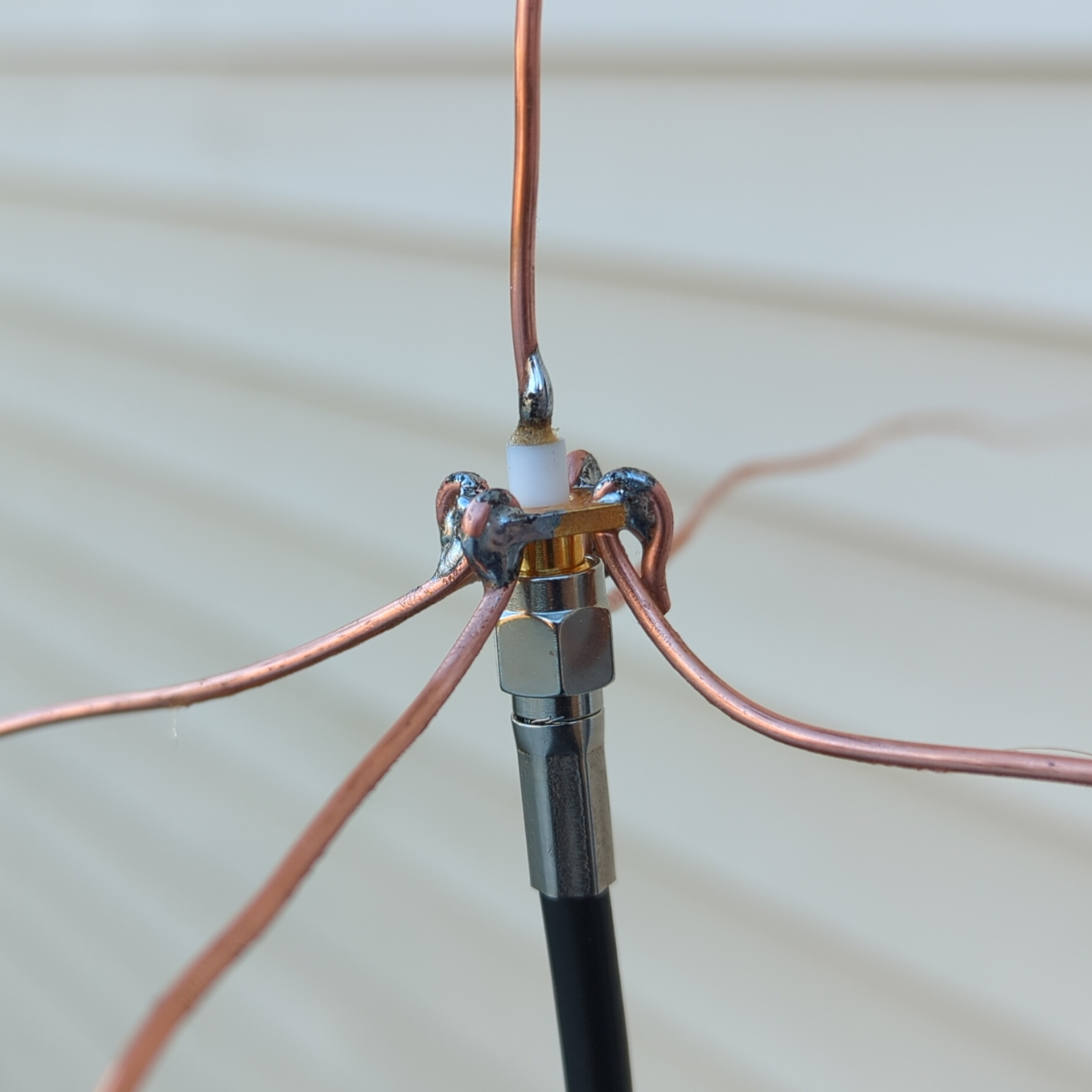
After the aluminum foil fiasco above, I decided to forget the assembly block thing and try to just buy a part that has good mounting design built in. I quickly learned that the connectors I had bought originally were meant for cables and not for termination to a bare conductor or other connection. There are several other varieties of connector, and one of them has four mounting holes and a brass body that’s all grounded. It even has an extended insulator on top with the pin exposed. It was perfect for my use case, and it has performed well, all for practically the same price as the other connectors.
After the nanoVNA, the most expensive item in this project was the crimping tool. I don’t really see why it had to be as costly as it was, but I can’t complain about its effectiveness. Between the crimping tool and the cable stripper (which was much less costly), connectorizing the coax was much easier than it might have been. I could definitely have tried to do a decent job of stripping and crimping with the tools I have, but with the right tools in hand the job was trivial, even fun. I don’t think this is the answer in all situations, but I’m pretty sure I spent less money here than I would have otherwise spent in equivalent time and frustration.
UPDATE 2023-04-06: A friend pointed out that handheld radios and their antennas are usually designed under the assumption that they will be used close to a human body, which can significantly affect the performance of the system. I did not account for that in my tests, which may mean that this antenna is better under real operating conditions than I thought.↩︎